

How Does A Bolted Repair Coupling Work

What Is a Coupling?
The shaft coupling is a mechanical element that joins two shafts together to accommodate misalignment of torque from one end to the other. In a mechanical system, a coupling tin be defined every bit a blazon of connection betwixt two rotating shafts that connect the driving and driven shafts together. The articulation between two shafts tin can be permanent or temporary.
In simple words, nosotros tin can say that couplings are used to connect input and output shafts in any power manual organization like gearbox shaft in machine tools is continued to the input engine shaft through couplings; Engine shaft with pump or compressor shaft, etc.
The function of a coupling is nigh the same as that of the clutch, but clutches are temporary joints, whereas coupling joints are permanent connections. The basic purpose of a coupling is to permanently connect two shafts. Shafts in power transmission are not always linear connections; They can exist parallel, with intersecting axes and slight eccentricity.
Therefore a different blazon of Coupling is used in mechanical power transmission. Co-ordinate to the requirement and functions, dissimilar types of couplings are used.
The basic characteristics of different types of couplings are almost the same, which are as follows: Power Transmission, Join the misaligned shaft, Reduce tremors and vibrations, Easy to assemble and disassemble.
Shafts can be connected in three ways considering mostly, in three dissimilar ways, shafts are aligned; these are when both shafts are parallel, or we can say that some eccentricity exists between them, collinear shaft and The terminal 1 is intersecting the shaft with some athwart deflection.
Besides, Read: What Is Composite Material? | Why Use Composites? | When Should You Use Composites? | Natural and Synthetic Composites
What Is Shaft Coupling?
The shaft coupling is mechanical components that connect two rotating shafts, such every bit the driving shaft and the driven shaft, for the purpose of transmitting ability. It is used in motors, pumps, generators, and compressors. The shaft coupling is a device used to connects ii pieces of rotating equipment or shafts for the purpose of transmitting power from one shaft to some other.
They are besides used for many purposes, mutual among which are the following:
- To provides for the connection of shafts of separately manufactured units such as motors and gearboxes and to provide for disconnection for repairs.
- To provide for the misalignment of a shaft or to introduce mechanical flexibility.
- To reduce transmission of shock load from one shaft to another.
- To get-go the protection confronting overload.
Also, Read: What Is Pulley? | How Does a Caster Work? | Function of Pulley | Types of Caster | Types of Apartment Belt Pulleys
How Does a Shaft Coupling Work?
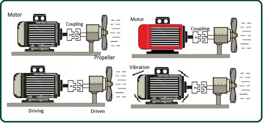
You can connect two shafts together by Coupling, as shown in the movie to a higher place. No problem, shaft diameters are different. According to the above diagram, the motor is the driving side, and the propeller is the driven side.
The Coupling does non transfer the heat etc., of the motor to the driven side. The Coupling absorbs shock and vibration from existence moved; this will help prevent damage to surrounding components.
Besides, Read: What Is Caster? | How Does a Caster Piece of work? | Role of Pulley | Types of Pulley | Types of Apartment Chugalug Pulleys
Types of Shaft Coupling:
The different styles & types of shaft coupling are summarized below.
#ane. Beam Coupling
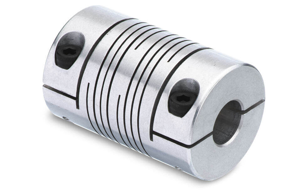
Axle couplings have unmarried or multiple helical cuts in the coupling body that can typically adapt parallel misalignment up to 0.025 inches and angular misalignment up to 7 degrees. They are primarily used for speed control applications where torques are typically below 100 inch-lbs.
Zero backlash designs ensure positioning accuracy between the available driving and driven shafts. The materials used to manufacture beam couplings also touch their performance and suitability for specific applications such as food, medicine, and aerospace.
The materials are typically aluminum alloys and stainless steel, merely they can also be made in acetal, marring steel, and titanium. The near common applications for robotics are connecting rotary encoders to shafts and move controls.
#2. Bellows Coupling
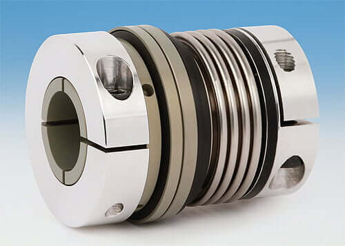
Bellows couplings are also suitable for speed control applications. These consist of multiple convolutions of metal that provide loftier torsional stiffness, which is of import for positioning applications.
Torsional stiffness reduces the level of athwart & parallel misalignments they can accommodate compared to beam couplings, although the torque transmission efficiencies are approximately the same. They contain multiple metal fixtures that provide loftier torsional rigidity, which is important for the application conditions.
Torsional stiffness reduces levels of angular & parallel misalignment that they can accommodate with beam couplings, although the torque transmission capability remains the aforementioned.
#3. Chain Coupling
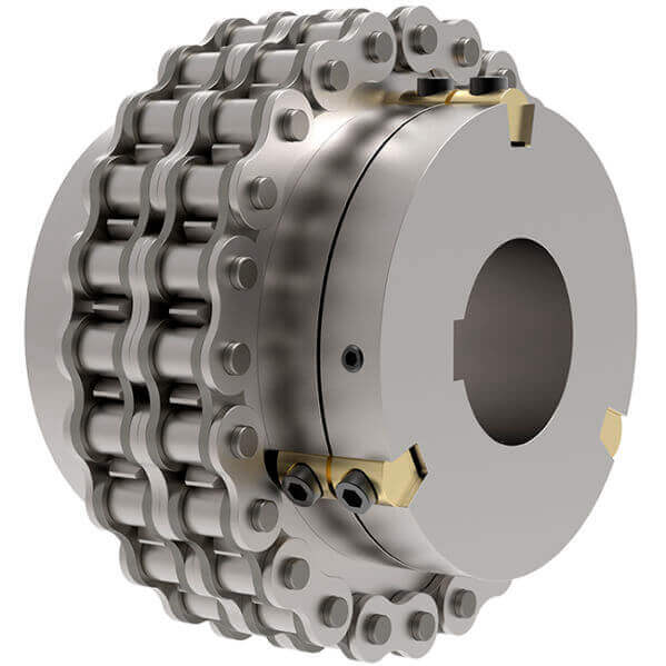
Chain couplings are suitable for ability manual applications and are used to transmit power in the hundreds of horsepower range. Angular & parallel misalignment allowances are typically two degrees and 0.015 inches, respectively.
Specialized chain couplings use special chain sprockets and double-wide roller chains whose clearances permit the blueprint to operate equally a flexible coupling.
#4. Jaw Coupling
Curved and directly jaw coupling is used for both motion controls and light power transmission applications & consists of pairs of multi-jaw hubs with an elastomeric spider. The design allows for backlash-free torque manual.
Accommodation for parallel misalignment typically reaches 0.01 inches, and angular misalignment reaches approximately ane degree. Elastomeric spiders requite this Coupling some damping capacity, and oft spiders are available in different durometers to attribute specific properties to dissimilar couplings.
This Coupling frequently operates without lubricant and tin can transmit torque to grand in-lb. A jaw coupling is a material flexing coupling that transmits torque through the compression of an elastomeric spider insert placed between two intermeshing jaws.
- The flex element is usually made of NBR, polyurethane, hydrogel, or bronze, Adjusts for misalignment, Transmits torque, Used to reduce torsion (vibration), Low torque, general-purpose applications.
#5. Diaphragm Couplings
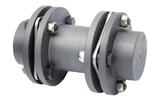
The Diaphragm couplings use a single or single series of plates or diaphragms for flexibles members. Information technology transmits torques from the outside diameter of flexibles plates to the within of the spool or spacer piece and then from the inside to the outside diameter.
Typically they apply ane or more than flexible metal complex discs that transmit power to an internal spacer shaft so dorsum to the operated machinery via another diaphragm stack.
A major advantage over gear-type couplings is their lack of lubrication requirements. Diaphragm couplings are capable of high torques transmission and high-speed operation.
#half-dozen. Disc Coupling
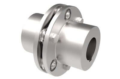
The Disc couplings utilize single or multiple discs & single or double stages that bolt to the shaft hub. These are used for power transmission and rely on the flexibility of their thin metal discs to transmit torque and suit angular misalignment. They are not especially good at managing parallel misalignment.
These couplings typically include two hubs, two-disc packs, and a eye member. A single-disc pack tin accommodate angular and centric misalignment. A two-disc pack is required to accommodate parallel misalignment.
- Allows athwart parallel and axial deviance, Has a existent limited end float design, A zero-feedback pattern, High-speed rating, and residuum.
#seven. Oldham Coupling
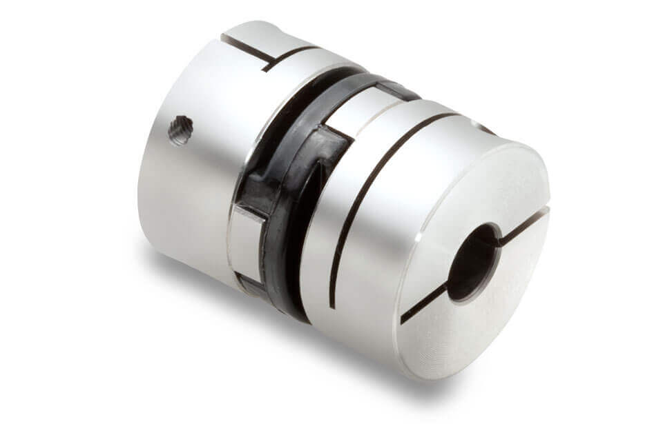
Oldham couplings handle loftier levels of parallel misalignment due to their sliding element design. The use of an elastomer center element instead of metal is popular in modern versions. Some manufacturers claim the ability to tolerate five-degree angular misalignment through the use of cylindrical, rather than rectangular, sliders.
Two discs, typically made of aluminum or stainless steel, are fastened to either side of the drive, while the third is one of several different plastics sandwiched betwixt the tongue-and-groove design. Tongue and groove on one side is natural language and groove on the other.
Springs are ofttimes used to reduce the backlash of the Coupling. Oldham couplings have several other advantages, including their compact size and the ability for electric isolation via a plastic center disc.
Tin can act as fuse for coupling automobile. If the torques limit is exceeded, the middle discs of the Coupling will break first, thereby fugitive torque manual and potential damage to more expensive motorcar components.
Also, Read: What Is Chain Drive? | Chain Drives for Transmission | Types of Chain Drives | Chain Drives in Auto Vehicles
#8. Schmidt Coupling
Schmidt couplings are specifically designed to operate on offset shafts. They are not flexible couplings in the strict sense, designed to conform minor misalignments in shafts that are theoretically parallel and foursquare to each other.
Schmidt couplings are used in papermaking, printing, & similar machines and act like a 1:1 gearbox in a more compact infinite.
#9. Bushing Coupling

The bushing flexible coupling is a modification of the rigid coupling type flange coupling. The coupling bolt is known as a pivot. Rubber or leather bushings are used over the pin. As well, there is a difference in the texture of the two parts of the Coupling. There is a v mm clearances remaining between the faces of the two halve of the Coupling. And at that place are no rigid connections betwixt them, & the drive is throughs compressed rubber or leather bushings.
#10. Clamping Coupling
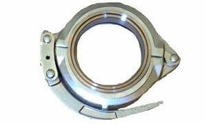
Rigid i- and two-piece clamping couplings lack housing for shaft misalignment and are popular for boring or intermittent shafting arrangements where alignment is not a business. They are the simplest grade of shafts coupling and, in addition to lacking misalignment tolerance, are cheap zero-backfire devices.
#11. Universal Coupling

Universal Coupling is used to connects 2 shafts whose axes intersect at a modest bending. The angle of two shafts may be constant, but in actual practise, it changes when momentum is transferred from one shaft to another.
The main application of universal or hooks Coupling is constitute in transmission from the gearbox to the differential or dorsum axle of an car. In such a case, nosotros utilize the Coupling of two hooks, one that connects to the gearbox at 1 cease and the differential at each end of the propeller shaft at the other end.
The Coupling of hooks is also used to transmit power to the various spindles of many drilling machines. It is used equally a knees joints in milling machines.
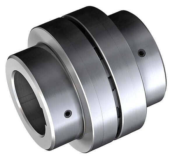
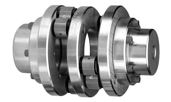
#12. Gear Coupling
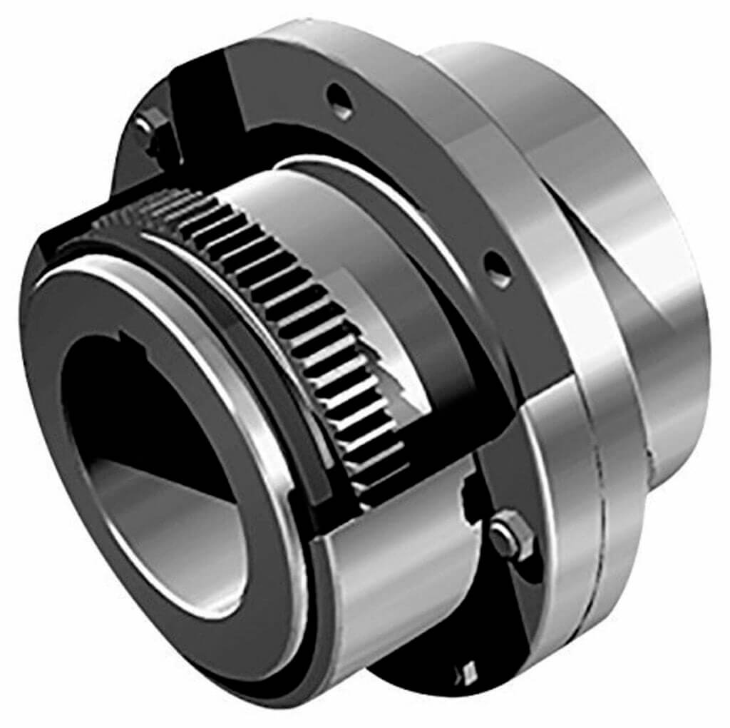
The gear coupling transmits the greatest torque and highest amount of torque to the smallest diameter of any flexible coupling. Each Coupling consists of ii hubs with large external gear teeth.
Hubs are forged with two internally trimmed sleeves that are bolted together.
Gears couplings accommodate angular & axial misalignment past moving and sliding the crown gear teeth against the mating sleeve teeth. Parallel misalignment is accommodated by two adjacent hub/smooth flex points.
Gear couplings require periodic lubrication depending on the awarding. They are vulnerable to lubrication failures, but if properly installed and maintained, these couplings have a service life of three to 5 years, and in some cases, they tin last for decades.
#13. Grid Coupling
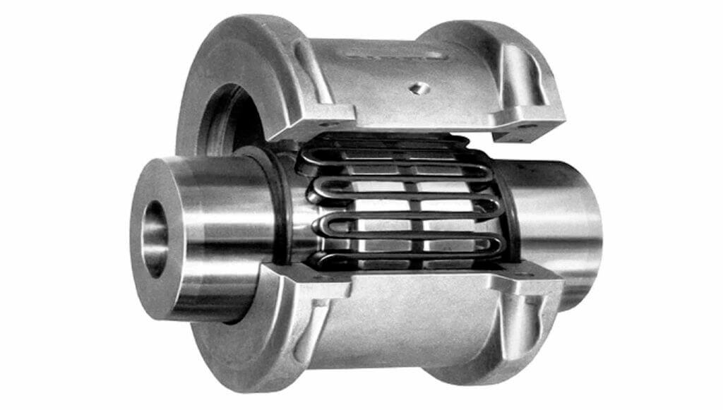
The filigree coupling consists of two radially slotted hubs forged with a serpentine strip of spring steel that allows the grid to bend and flex with the steel strength of the elastomer.
Grid couplings transmit torque from i hub to another through a tapered grid rocking and sliding in parallel mating hub slots and accommodate axial misalignment.
The grid cantankerous-section is generally thinner for better hub contact and easier assembly. As there is motion betwixt the contact hub and the grid metal parts, lubrication is required.
#xiv. Split Muff Coupling
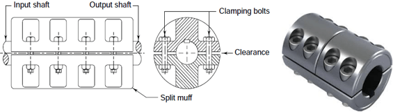
Splits muff coupling, In this case, the muff or sleeves are made in two halves and bolted together. Half the muff is made of cast iron. The ends of the shafts are designed to be spaced autonomously, and the same key is fitted directly to the keys of both shafts.
Half of the muff is fixed from beneath and the other half from in a higher place. The ii parts are held together using balmy steel studs or bolts & nuts. The number of a bolt tin be ii, 4, or six. The nut is recruited in Muff Casting Bodies.
This Coupling can be used for heavy-duty & medium speeds. The advantages of this Coupling are that there is no need to change the position of the shaft for Coupling or assembling.
Also, Read: What Is Welding? | How Does Welding Piece of work? | Types of Welding | Different Welding Joint Types | Types of Welding Joints
Application of Couplings:
- Sleeve and Muff Coupling Line shafts in power transmission.
- Clench or split-muff or pinch coupling line shaft in power transmission.
- Flange coupling for alignment accuracy, east.grand., Marine.
- Bushed Pivot Flexible Coupling Used to connect which have small parallel misalignment, athwart misalignment, or axial misalignment. car
- Universal Coupling Used to transmit rotary motion or power, due east.m., shipping, driveshafts, etc.
- Oldham'southward Coupling Useful in applications where parallel misalignment exists, east.g., Printing Application.

Source: https://mechanicaljungle.com/what-is-a-coupling/
Posted by: christiansencoputere.blogspot.com
0 Response to "How Does A Bolted Repair Coupling Work"
Post a Comment